I have many times looked at my old mobile phones (the ones that were cool because they had pixels instead of numerals) and have been wanting to use some of the parts.
I got inspired looking through my Arduino Basic Connections book, and found an instruction to control a Nokia 5110 LCD with an Arduino board. My phone is the Nokia 5210, so not a absolute match, but since the amount of pixels is the same I was hoping the same control circuit was used.


Opening up the phone, I was positively surprised how easy it was to disassemble. It seems the strategy has been to make tiny modules that fit together without needing screws. What I had in my hand in the end, was the LCD with a flexprint attached to it.
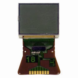
Then I needed to determine if it the control IC was the same, and if so, identify the pads of the flexprint. It took quite some time and advanced deduction (combined with a bunch of googling of course), but my conclusion was that it is indeed possible, and the pinning (padding?) is shuffled compared to basically any other LCD (even the ones that look VERY similar). The pinning turns out to be as follows (counting for left to right in the picture above):
pin 1 - LCD reset (RST)
pin 2 - (VOUT)
pin 3 - Ground (GND)
pin 4 - LCD chip select (CS)
pin 5 - Data/Command select (D/C)
pin 6 - Serial data out (DIN)
pin 7 - Serial clock out (SCLK)
pin 8 - Power in (VDD)
Using the schematic in the Arduino book I connected the LCD to my Arduino Leonardo (I guess any type type of Arduino would work).

Adafruit has made libraries to simply control a Nokia LCD. With them you can specify images pixel by pixel in the code, or even draw shapes like circles or triangles. I forked the git repository, since I needed to make some small changes. Namely, to change the order of the pins in the example code from:
// pin 7 - Serial clock out (SCLK)
// pin 6 - Serial data out (DIN)
// pin 5 - Data/Command select (D/C)
// pin 4 - LCD chip select (CS)
// pin 3 - LCD reset (RST)
Adafruit_PCD8544 display = Adafruit_PCD8544(7, 6, 5, 4, 3);
To:
// pin 3 - Serial clock out (SCLK)
// pin 4 - Serial data out (DIN)
// pin 5 - Data/Command select (D/C)
// pin 6 - LCD chip select (CS)
// pin 7 - LCD reset (RST)
Adafruit_PCD8544 display = Adafruit_PCD8544(3, 4, 5, 6, 7);
Time to try it out, and indeed it works! The example graphics from Adafruit starts filling the screen.


I fast noticed, however, that the graphics was flipped in the x direction. A small fix in the library code fixes this. You can see a file comparison of the change here.
Now let's display something interesting. I have a vision that sometime in the future I will make a windmill, and for that I would need a regulator, taking care of charging a battery. It would be cool to include a display the regulator, indicating amount of power produced, remaining battery juice and so on. A battery indicator can be simply created using the rectangle drawing functions of the Adafruit library, called drawRect() and fillRect(). I decided to also make a picture of a windmill, that would turn when there was wind, and be still when not. For this I made three pictures, to be displayed after each other, simulating turning of the blades.
To simplify making the bitmaps significantly, you can make the images in Gimp and save in .xbm format. The file can then be opened in notepad and the text simply copied into the Arduino file. For it to work I first changed the Adafruit code to allow this, but then I realized that meanwhile an update had been made to the git repository, to allow exactly that. Behold the result:

Love the #8 wire ingenuity here. I've just been tinkering with an old cell phone display and was wondering the same thing- great use of the LCD, I'll have to see if I can determine the pinning of mine and put it to work!
ReplyDeleteThis comment has been removed by a blog administrator.
ReplyDeletecan i get the pin connection diagram please?
ReplyDeleteThis comment has been removed by a blog administrator.
ReplyDeleteThis comment has been removed by a blog administrator.
ReplyDelete